Functions and Types of Instruments
1. Oscilloscope (Transient Analysis)
1) Observation of Signal Waves
The waveform of the circuit's voltage or current is analyzed in time and displayed in a graph.
2) FFT (Fast Fourier Transform) Function
The elements of each frequency included in a signal is analyzed and displayed in a graph.
3) Changing DC/AC/GND Input
DC: The waveform including the DC element is displayed.
AC: The waveform excluding the DC element is displayed.
GND: The standard of 0V is confirmed. A waveform is not displayed.
4) Trigger Sweep Function
When the set polarity and level of the observed signal are exceeded, a signal waveform is displayed.
5) Current Probe Function
Displays the direction of the wiring's current and the current's waveform.
6) Signal Data Output Function
Outputs the time and current or voltage as a value with a cursor.
7) Sound File Creation
Creates a Windows sound file from the observed signal's waveform and outputs it in a file.
8) Creation of Signal Files
Creates a text file from the observed signal's waveform data.
2. Frequency Analyzer (Frequency Analysis)
1) Observe the Circuit's Frequency Response
Analyzes a circuit's frequency response and displays the gain and phase in a graph.
2) Change Frequency Response Display to Log and Linear
Changes the step of the frequency analysis to Log and Linear when the frequency response is displayed.
3) Frequency Response Data Output Function
Outputs the gain and phase of the frequency response as a value with a cursor.
4) Creation of Frequency Files
Creates a text file from the frequency response analysis data.
3. Digital Multi-Meter (Direct Current Analysis)
1) Measurement of DC Voltage and Current
Displays several Hz or less of a signal's voltage or current as a numerical value.
2) Other Measurement Functions
Displays the junction capacitance of semiconductors, power consumption of power supplies or resistors, and the amount of charge in capacitors.
3) Current Probe Function
Displays the direction the wiring's current and the current's value.
4. Signal Generator
1) Signal Types
Generates 6 types of signals such as sine waves.
2) External Input Signals
Can output a Windows sound file as a signal.
Can output a signal file with an optional pulse waveform
3) Signal Output
Can changes between voltage output and current output.
4) Internal Resistance Settings
Can set the value of internal resistance.
5. Direct Current (DC) Power Supply
1) Output
Can change between fixed voltage and fixed current outputs.
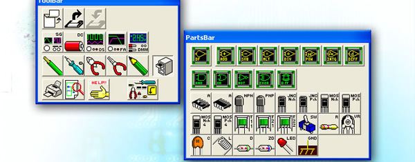
Electronic Parts
All the parts can be used simultaneously and simulated whether they are analog or digital.
1. Analog Parts
Resistors, capacitors, coils and semiconductors such as diodes, transistors and FET etc and operational amplifiers are available.
Switches can be changed between ON and OFF, and LED will flash if they are set with a fixed current.
The position of a variable resistor's wiper can be changed.
Digital or virtual parts can be used simultaneously with analog parts.
2. Digital Parts
AND, OR, NOT, ExOR, D-FF are available.
The logic of each input and output terminal can be easily reversed with the pencil cursor.
Analog or virtual parts can be used simultaneously with digital parts.
3. Virtual Part
A digital filter (FIR filter) can be created and used.
The four rules of arithmetic units and power, integral, and differential units are available.
Analog or digital parts can be used simultaneously with virtual parts.
Other Functions
1. NetList Output
Outputs each parts connection state by its number of nodes as a text file.
2. Insertion of Text
Text can be easily inserted on a schematic.
3. Circuit Bitmap
A bitmap can be created of a specified circuit area or of an instrument and sent to the clipboard. It can then be used in other applications.